In a mid-high complexity design, you probably have 5 or more (maybe a lot more) rails to manage. Those rails probably have sequencing requirements — in both the power up and power down directions. There’s a good chance you have several district power states, and need to move between them.
You need to verify that your supply sequencing is correct, across all power-state transitions.
Step 1 - make a printed “map” of the board
If you’re like me you probably have spent a lot of hours pulling up Altium finding where to probe a particular net for the 20th time. Instead, try this:
Take good pictures of your assembled boards, on both sides. The optimal way to do this, in my experience, is use a ring light (these are cheap) at a 90-deg angle, and take the photo with your phone.
Turns out a laser printer does a decent job printing these images — I most recently used the B&W High Contrast filter before printing - built into the Photos app on Windows. For a large board you might need to split into several images, and ideally tape them together. If you were thinking ahead you could get a large image printed online - would be nice to have this as part of the board release proceedure.


Step 2 - set up a robust probing solution
It’ll be worth your time later to set up a probing solution that isn’t hyper delicate or that requires constant under-the-microscope soldering.
Instead, pick a decent probe-holding solution and get set up right. If you don’t already have one of these, get it right now. Hell, you should get three of them. Seriously!

Step 3 - probe all the rails and label them
Probe holding solutions like the PCBite are not perfect, but they are way better than nothing. Take the time so that your probing isn’t going to fall over in the slightest breeze.
If you have a usb cable, and/or other cables - make sure you’re set up to easily plug/unplug — without needing to plug/unplug them for the DUT! Otherwise, your probing is going to be continually falling over. You might consider a USB switch like this one, especially if you’ll be automating any sort of testing later.
Also - because this is endlessly confusing after the fact - take the time to label your inputs - both in the software, and ideally also with some labels directly on the wires. E.g. VBUS, 5V, 3.3V, 0.9V 1.8V_FPGA, etc.


Step 4 - pull up the requirements
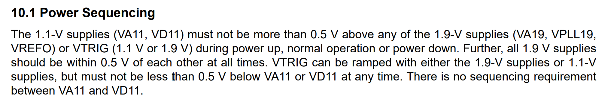
Ideally you have a great single-source-of-truth document set for your project, that includes a section dedicated to power, and power sequencing requirements. If not, create it!
Personally I like to include lots of screenshots from the datasheets — it provides more easily observable “audit trail” that will help out your design review and hopefully prevent continuous thrashing through all the datasheets. More on this topic another time.
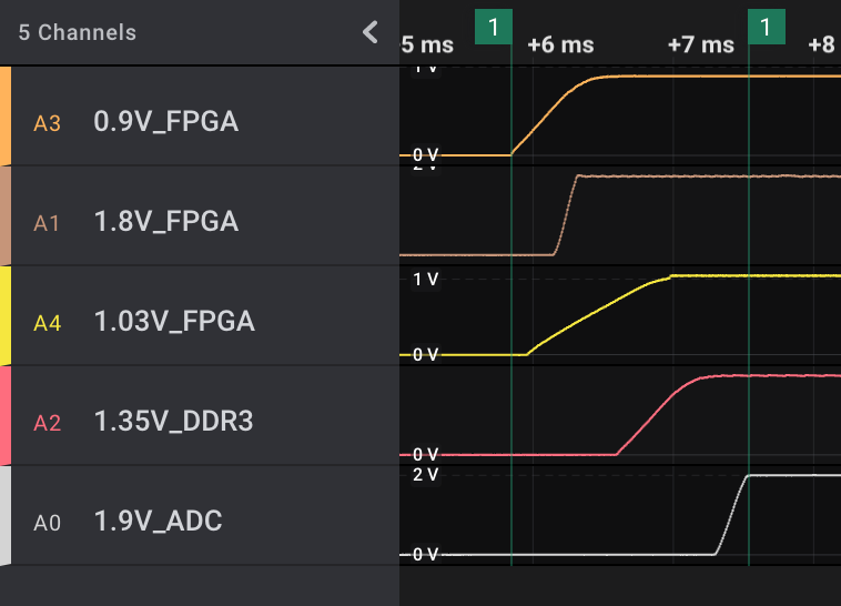
Step 5 - Arrange the channels to match the rail sequence
Wouldn’t it be nice if you could just glance at the screen and see if the sequence was good? Drag the channels into the sequence you expect.
Step 6 - make your board do its thing, while recording
You might have your recording constantly running all the time so you can see what’s going on — that’s what I do — but I like to restart the capture before doing something something I want to zero in on later. Otherwise it might not be super clear later when “the beginning” was.
Now, power up your board. Download the firmware, run the test script - make the board do its thing.
- Start a fresh recording
- Power up the DUT
- Exercise various power modes as desired
- Power down
- Stop the capture
Step 7 - Kick back and observe the flawless supply sequencing
Now that you have a recording of all your rails over an entire “power cycle”, you can pan and zoom around checking that everything is as it should be.
Be sure to capture any errata in your single-source-of-truth-for-all-project-errata doc. Grab screenshots of any issues and paste them in that doc.
Also, double check that you labeled all your signals correctly, ordered them correctly in the view, and that the sequence you observed actually matches the datasheet requirements.

Step 8 (optional) - think about how much better this process should be..
If you’re like me, doing this sort of thing brings to mind all sorts of ways this experience should be better.
- Super easy way to figure out where your to place your probes
- Super easy way to keep track of which probe is which net
- Super easy way to have the software automatically check your rail requirements
- Super easy way to clean up the presentation of these signals, e.g. so they are all overlayed with the same scale and different colors.
- more...
All in good time.
